|
|
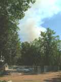 |
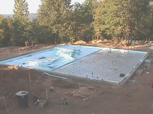
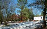
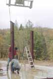
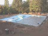
Fire! On the morning of Saturday, 22 July 2006, I saw a airtanker flying overhead toward nearby Rollins Lake. I could just see a wisp of smoke on the horizon in that direction. I immediately made three phone calls, to the head of our neighborhood association, to the local radio station, and to one of the managers of our emergency phone tree. A fire had just been reported at a campground at the near side of Rollins Lake, about 4 miles away and more or less upwind. This is a situation we all fear. There is a tremendous amount of dry fuel ready to go up in our region. I took this image in early afternoon, when the smoke was about at its peak. Fortunately, the winds were mild, as you can see from the picture. As there were no other wildfires competing for emergency services the fire was brought under control using a large rapid assembly of resources by evening twilight, with no injuries and no structures lost, and only 37 acres burned. We were lucky, very lucky. As I write this (8 September), a four day old fire, the Ralston fire, 20 miles to the east, is out of control at more than 2,200 acres in heavy forest. |
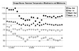 |
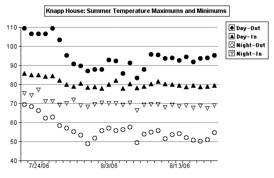
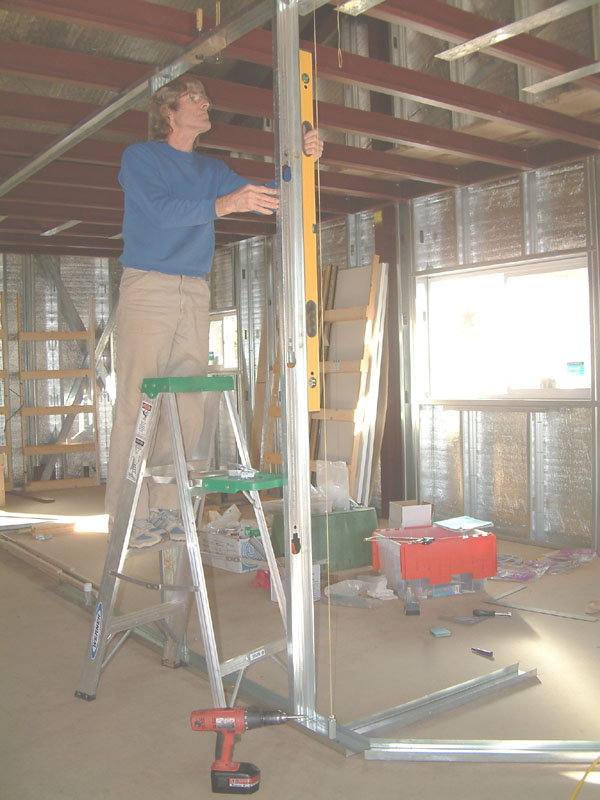
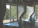
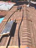
Thermal Performance - Summertime. At the end of the severe heat wave during July 2006 I started recording inside and outside high and low temperatures. Here is a graph of the extremes with the break in the heat wave obvious. I did not have window shades at this time. I put squares of the "low-e" wrap in the 9 south windows to reduce the insolation, and this kept the house temperature below about 85F. At night I was careful to open windows to cool the house by the mild night breeze. When the outside maximum is below 100F, the window inserts are unnecessary, and the patio doors with miniblinds are sufficient to control the heating. I have since bought cellular blinds for the bedroom and north windows, but I haven't decided about the south windows. I remind you that I will not have air conditioning. |
 |
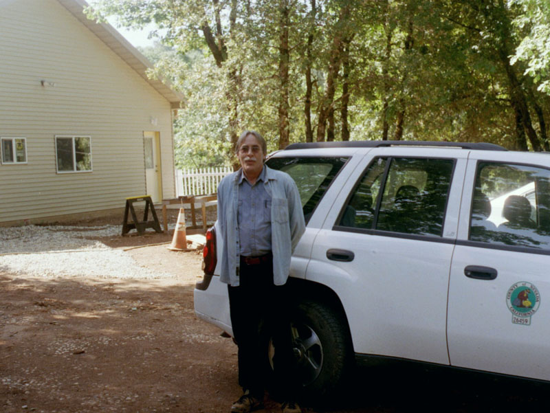
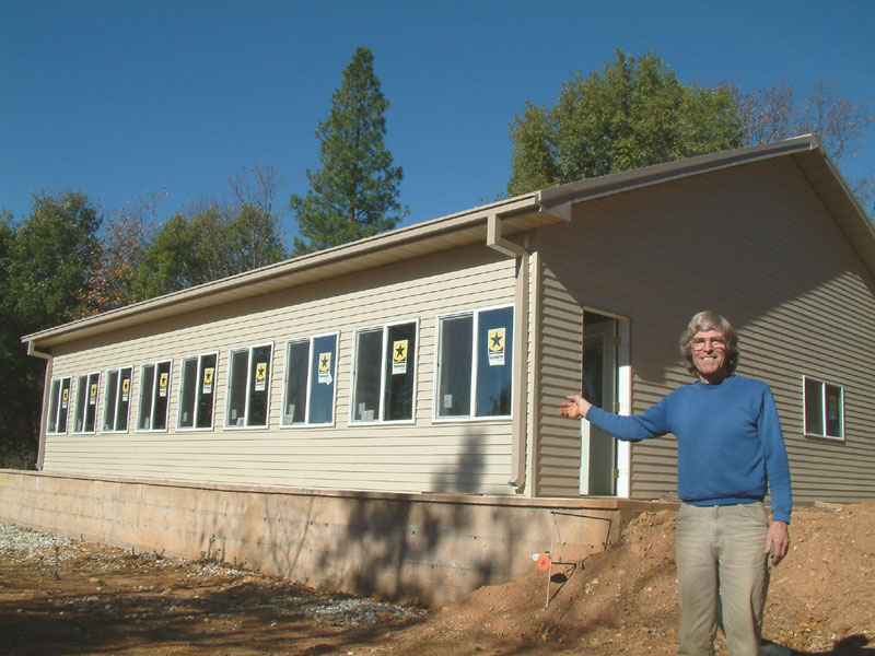
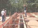
A picture of Building Inspector Peter Porterfield, who was my inspector for much of the construction. This picture was taken on his final visit, 26 May 2006, when the building passed its final inspection.
I want to express my thanks to the many members of the Building Department and Community Development Agency of Nevada County, California, for their patience and help in all phases of this project. I was treated with great consideration and courtesy. The house ended up better for their suggestions and advice. Although it was patently obvious (and I made no effort to hide the fact) that I was a rank amateur, everyone in the CDA and Building Department pretended not to notice. |
 |
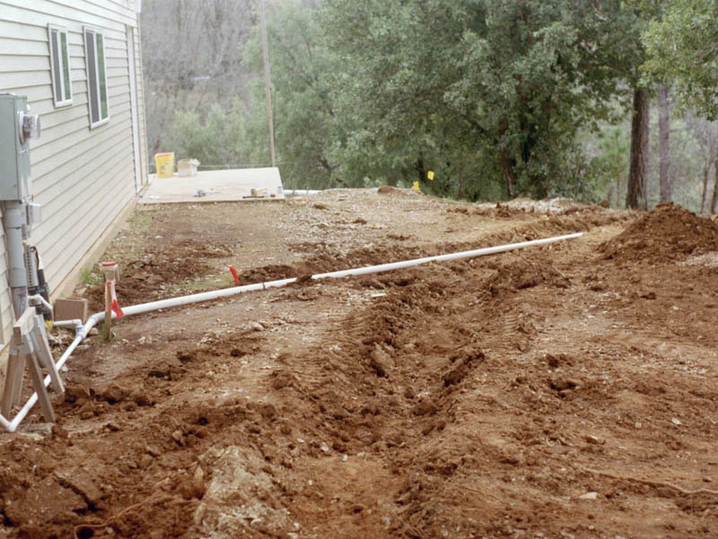
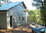
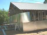
This is the west side of the house. The French drain will fill the trench in the center of the image. I made a similar trench on the east side helps move water from the north side of the house to the south along the natural slope. The white PVC piping is used to carry away the back-wash water from the two elements of the water treatment system. This piping merges into the French Drain in the center background of the image. |
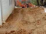 |
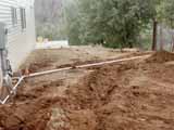
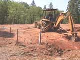
Drainage from the north side of the house is a problem during the winter/spring rainy season. I rented a backhoe to assist in the topology and to make a trench (of sorts) for a pseudo-French drain. This required two days' rental, for 16 engine hours. The first 8 hour day went mostly for me to become somewhat effective at operating the backhoe. As is obvious in this image of the north side of the house, my level of skill was not very high. |
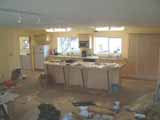 |
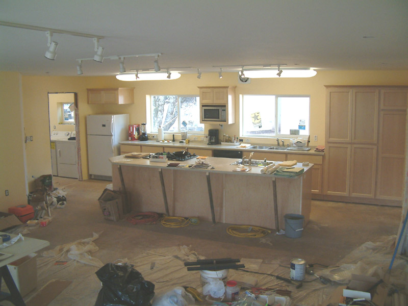
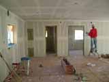
This is an image of the main room looking north. Note kitchen counters, built-ins, lighting, and laundry machines visible in NW utility room. I have been living in the house for about a month. What a pleasure to have a proper stove to cook with.
|
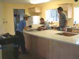 |
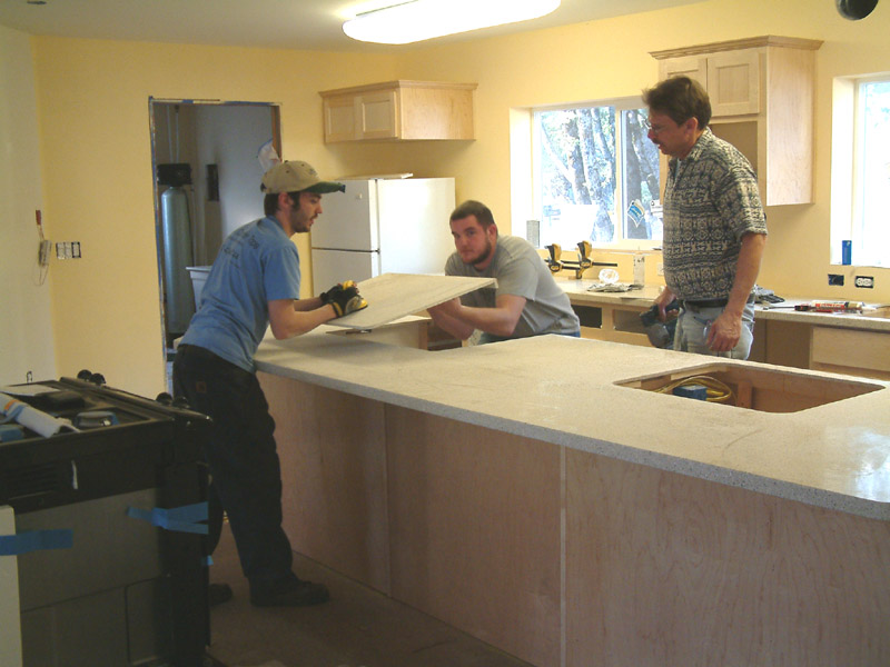
Here the countertops are being installed. Contractor Rod Lebbert, holding the jig saw, watches as his son Brian and helper Dustin lift the piece cut to make room for the slide-in stove. All counter tops are made of 1/2 inch acrylic from the WilsonArt Gibralter line. The island counter is extended out in cantilever fashion to the south to permit serving and eating meals. Note that my old refrigerator (from the Pasadena Oakdale house no less!) is now in its location in the far corner. I should have my living quarters transferred, informally at least, from the trailer into the house by the end of this month - February, 2006. |
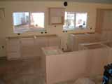 |
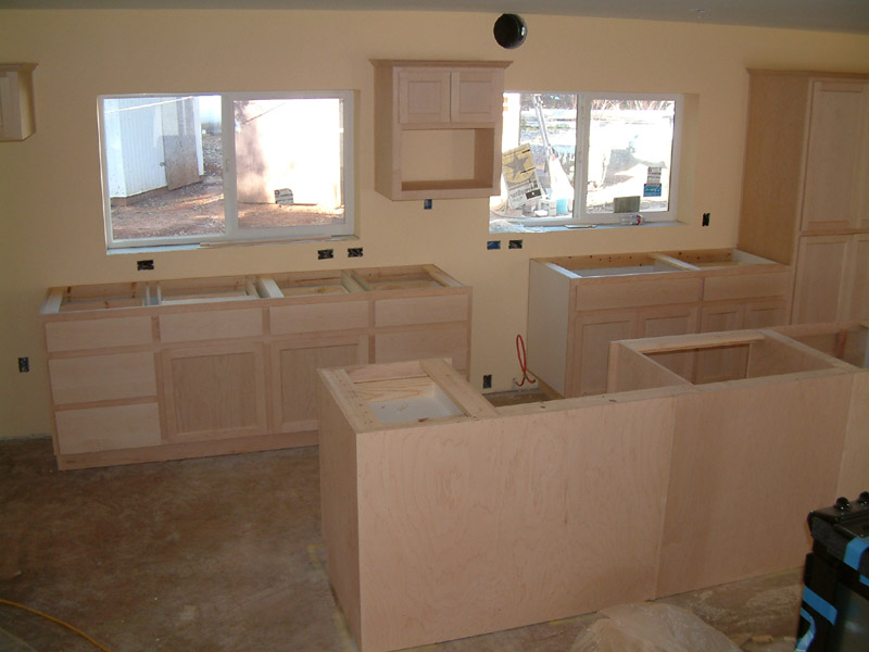
I contracted with a local cabinet maker to build the custom cabinetry for the kitchen and bathrooms. Here is a view of the kitchen cabinets with the island in the foreground. The stove will slide into the space in the island and the dishwasher into the gap in the cabinets along the far (north) wall. Above the dishwasher space is a wall cabinet for a modest microwave oven. Note the tall cabinets at extreme right. |
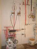 |
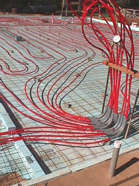
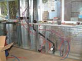
I constructed valving, interconnections, and the control electronics for the hydronic radiant heating system as soon as the house was insulated. This was a major milestone and a critical part of the entire house design, as the hydronic heating uses the multiple loops of PEX tubing cast into the concrete slab more than two years before, which is to say, an eternity ago. This image was taken at the first operation of one half of the HRH system. A similar subsystem is located at the opposite diagonal utility room. Each subsystem contains about 7 loops divided into two manifolds with separate circulating pumps which move hot water from the instantaneous water heater output into their respective manifolds and loops and return the cool water to the heater intake. The water heater is on the wall at the upper left, above the circular expansion tank. My control electronics are in the shiny chassis temporarily sitting on the box on the floor at left. Four thermostats, one for each circulating pump and respective loops, set the demand, and the control electronics contains digital timers to toggle the pumps so that only one in each pair operates at a time, toggling alternately. The slab has enormous thermal capacity and inertia, and the thermostats are programmed with this in mind.
I am most pleased to report that the HRH system appears to be a complete success, operating without modification to its theoretical design. This has given me a certain degree of satisfaction. |
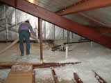 |
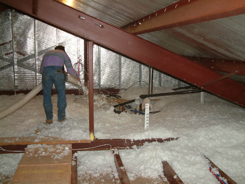
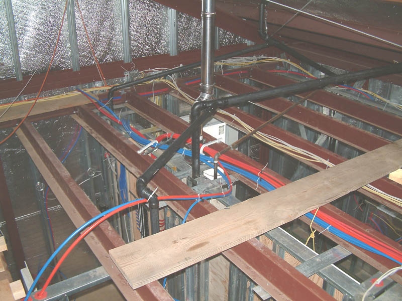
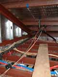
With the wall and especially the ceiling sheet rock completed I could finally have the insulation contractor return to blow in the attic insulation. This insulation was set at R 30, a degree of attic insulation greater than the level I set in my Title 24 energy analysis required for the building permit, but a degree worth the investment given the clear direction of future energy prices. This view is toward the NW end of the attic, and the blow-in nozzle is in the area where the hot water and hydronic heating tubing fan out from above the water manifold. The paper height gauges are for setting the insulation thickness during bolw-in. Note the heavy red iron rafter, one of two topping the central structural box, and the hanger which is connected to a horizontal beam from which the joists are attached. The red iron members bear all structural loads, allowing a clear span and non load-bearing walls. |
 |
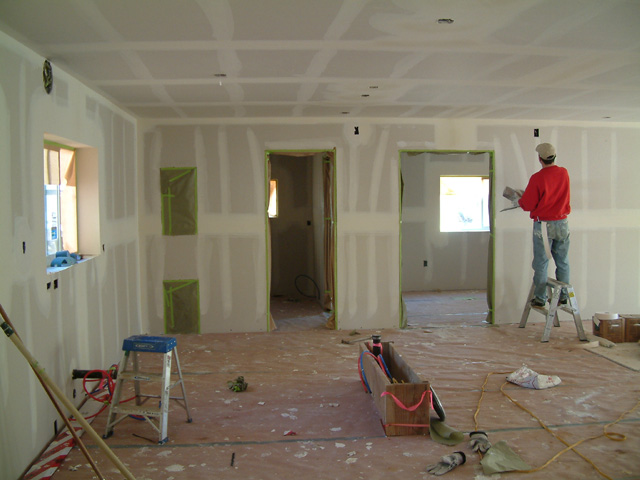
Here one of several craftsmen is finishing taping the drywall. The house is beginning to look like a house. By this time, mid-December, 2005, it is becoming clear that I will not occupy the house for a couple more months. But the end is in sight, however distantly. |
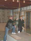 |
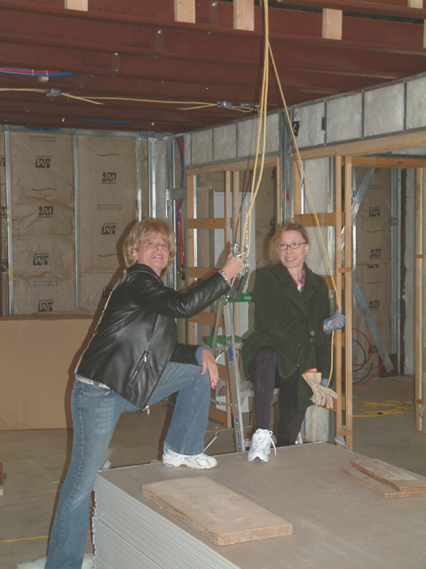
A major milestone in early December, 2005. Betty (on right) and her sister Bonnie are posing after helping me lower the last of the heavy 2x12 planks from the attic area, where they had served as catwalks. This was the last use of the attic block and tackle, which I removed in anticipation of the dry wall work. The gals have their feet on one of the piles of sheet rock, already delivered. Note that the walls have been insulated with fiberglass batts.
The insulating job and the dry wall job were done by contractor. There is no way that I could have done the dry wall, not only because I lack any experience for a highly skilled task but also because by this time my shoulders were damaged from over-stressing. |
 |
I provided Schedule 80 PVC conduits in a number of locations around the perimeter concrete stem wall for communicating electrical and water services to outside destinations. Two such conduits run about 30 feet to the nearby hut containing the well pump and pressure tank, one conduit for the main water line and one for electrical cables. This image shows the electrical cables (30 amp Romex, telephone, ethernet, television, etc.) being pulled down into the conduit in the far wall. |
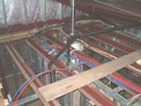 |
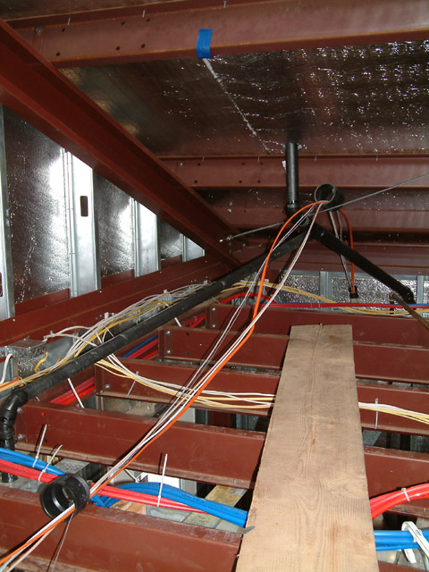
An image taken in mid August, 2005, of the attic infrastructures above the plywood wall of the utility room. Visible are bundles of 3/8 and 1/2 inch PEX tubing emerging out of the top of the wall at mid-left. In upper center is the flue for the tankless water heater, the flue in stainless by code due to the high combustion temperatures. The Romex cabling also emerges at the distant wall above the circuit breaker box below. |
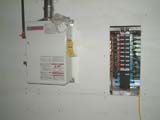 |
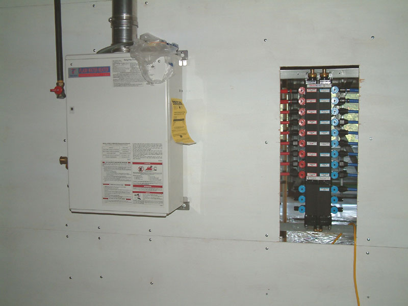
Here is the other side of the water manifold, on the right in this image. This wall, in the NW utility room, is painted plywood, installed in lieu of sheet rock so that I can attach major plumbing devices. On the left is the Tagaki tankless water heater, which fires up using electronic ignition whenever there is water drawn from the hot side of the manifold. The water lines have not been installed to the water heater. The controls and pumps for the radiant heating system will be installed on the wall to the left of the Tagaki. I hope to get the heating running before deep winter. |
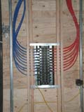 |
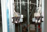
This is the rear of the parallel water distribution manifold. Connections to the PEX tubing are by aerospace crimp connectors. Each manifold port has an individual shut off valve; there are no valves at the destination appliances, and each port serves only one water use. I chose Vanguard Piping for the parallel water system components. |
 |
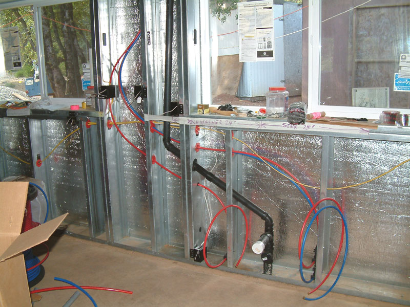
Rough plumbing. A view of the north wall of the kitchen area. The dishwasher and double kitchen sink will be built in at image center. Note the water distribution in PEX tubing, red for hot and blue for cold. No PVC or copper. Sharp eyes will spot the Romex cabling and boxes for switches and receptacles. The vent is for the sink/dishwasher drain, and the dog-leg dodges the window. |
 |
Rough electrical inspection was passed in mid July, 2005. Naturally, I have a complex system, using more than 2500 feet of Romex! I spent a lot of thought on how to provide many built-in lighting systems and controls and remote power (e.g., television monitors) outlets. Thus I include many three- and four-way lighting switches, some with dimmers. There are many ceiling fixtures, and I included wiring for future external (e.g., patio) functions. Here is a typical complicated set of lighting switch boxes, two quad boxes on each side of the sunspace/living area wall. Note the many tags with cables labelled, an absolute necessity for installation of the complex switches and dimmers. |
|
Cancer status 17 August 2005: The post-surgery pathology report on the tissue showed a perforated capsule, some adenocancer in the (removed) seminal vesicles, and one positive margin, implying that some localized cancer may remain. This bad news means that a relapse may happen within some years, but the statistics are uncertain. I am on a six month adjuvant treatment of chemical castration by testosterone suppression in order to inhibit adenocancer. I will have frequent PSA testing for some years, and at the first sign of any measureable PSA I will undergo salvage radiation treatment. Aside from this minor issue I am in great health! I returned to work on the house in early June. Five months after the surgery, I am nearly continent. |
|
My girl friend/partner Betty Vendig has been most wonderful and is one of the sources of my strength.
My biggest problem during recovery is not to exert myself. House construction, mainly finishing the rough electrical and installing the rough plumbing, will not resume until around June. Please stay tuned. |
 |
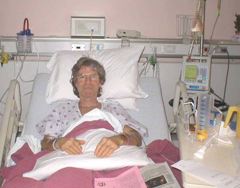
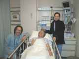
Betty took this image the day after surgery. Just before I was anesthetized, I had asked that the operating room be cleared of any supporters of G.W. Bush, but I have not been able to verify compliance with this request. In any case the surgery, which lasted about 3.5 hours, seems to have gone quite well. My autologous blood unit was not needed. I conclude that, in addition to careful political screening of participants at the operation (Karl Rove take note), building a house is excellent physical preparation for a good outcome from intense surgery. The resident docs were so happy with my recovery, or were so offended by my presence, that they insisted that Betty take me away to her home before 48 hours had passed. Lymph nodes were negative. The urologist/surgeon, Dr. V. Gajendran, said he was able to spare one side of my nerves. I await the post-op pathology report. |
 |
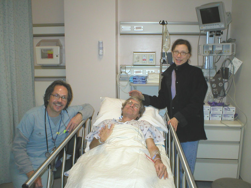
Work was suspended in March, 2005, after I was diagnosed with moderate-early prostate cancer. After tests and consultations, I chose to undergo a radical retropubic prostatectomy at my health provider, Kaiser Permanente (N. Calif.), a non-profit institution which could well serve as a model for a national health system with universal coverage, rather like the Canadian or EU systems, if ethics and family (i.e., christian) values finally prevail over this country's currently dominant stockholder-paying laissez-faire capitalist HMO/insurance system, which most agree is broken.
Friday, 25 March 2005. Betty is attending when Kaiser nurse Robert (politically liberal like us) installed my first IV. This is 30 minutes before surgery. |
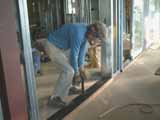 |
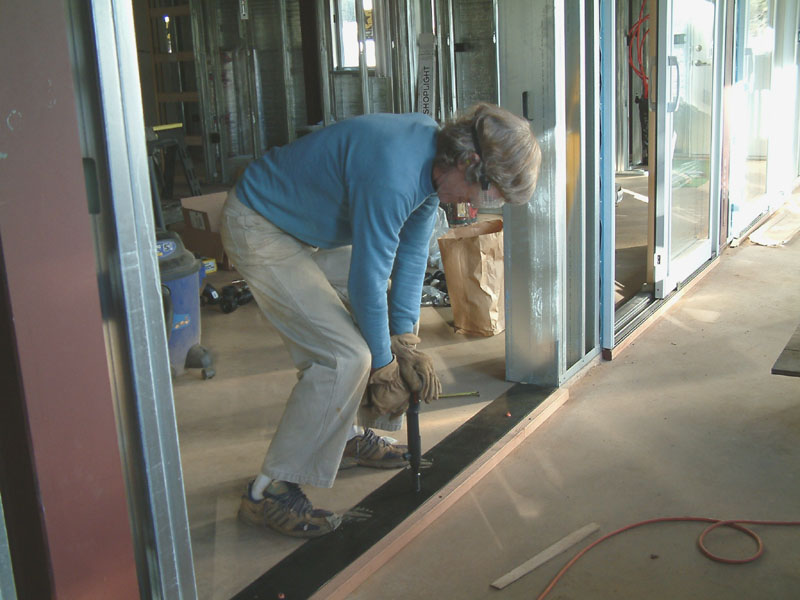
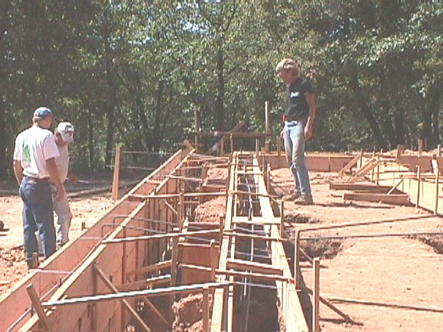
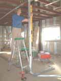
Neighbor and community activist Sandy Jansen helped me unwrap and move each of the four Pella patio doors into position at the rough openings in the interior south wall. These 6-ft wide sliding glass door assemblies are very heavy. Here I am shooting nails to secure neoprene gaskets to the concrete at a patio door threshold. Goggles, earplugs, gloves are protection from the 22cal. nail gun. A couple of the patio doors required shimming, as the concrete was not quite flat and my rough openings were not undersize.
During February and March 2005, I worked on the rough electrical installation, running something like 1500 feet of Romex. This job is 80% finished. I have numerous 3-way and 4-way switch complexes. So far I have used more than 100 tags to identify cable ends. Bushings are required in all wall penetrations for electrical and water lines. |
 |
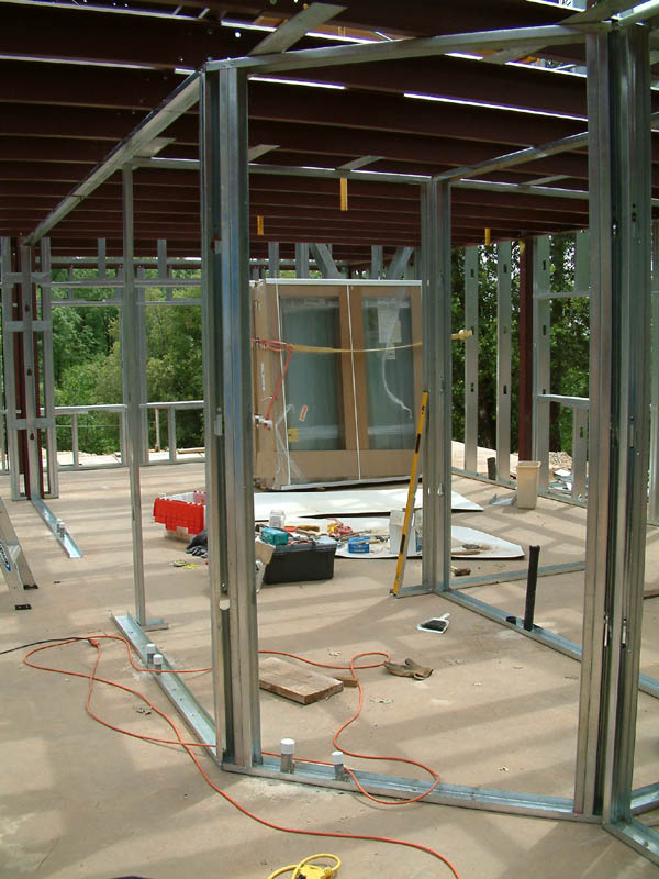
With the exterior finished, I returned to the interior walls on the east side. Here I am installing the tracks and the first studs of the 4-in walls. This view is looking from near the line of patio doors toward the guest bedroom and guest bath in the corner beyond.
I set the interior walls in a multiple-step process. First I lay out the wall center lines and doorway dimensions in pencil from my drawings onto the concrete slab, paying careful attention to the locations of embedded hydronic tubing using the drawings and my photographic record. Then I fasten the steel wall tracks, with door openings, onto the slab floor by shooting nails and installing anchor bolts. Then I locate the locations on the joists of the upper wall tracks using the plumb line to extend the wall centerlines upward. Finally, I use self-drilling screws to attach the upper tracks below the joists. Unlike the exterior walls, where 24-inch centers are used, the interior studs are on 16-inch centers. |
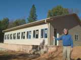 |
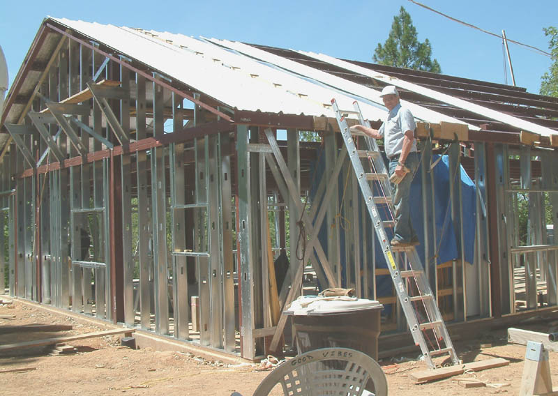
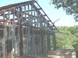
This self-timed image was taken on 24 November 2004. It shows the house with the external envelope finished, save for a few minor final tweaks. The roof trim is part of the Heritage package and includes not only all the gutter materials but also formed and painted light steel pieces to rain-proof the perimeter of the roof. The trim installation required careful trimming and fitting as well as applications of sealant. Installing trim along the rakes and, especially at the peak end boxes, was downright dangerous, and I took great care to go slowly. A very wet and stormy winter season proved the envelope to be rain-proof. This was very satisfying for me, and it allowed me to continue construction of the interior during the winter, except when temperatures fell below about 40F, which I found to be too cold for my hands. |
 |
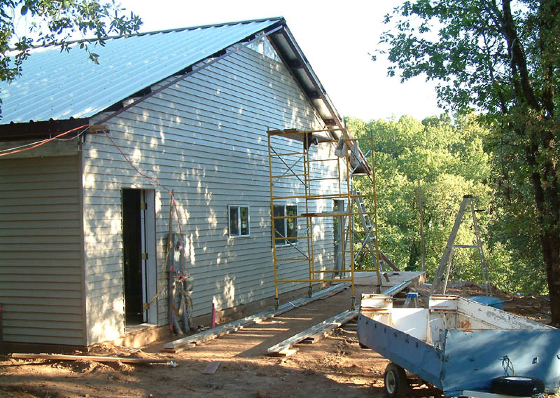
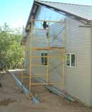
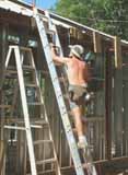
Siding for the west endwall is almost finished. A ladder atop the scaffolding is required to finish the high area under the peak. Note second pair of tracks for the scaffolding. 25 September 2004.
The next task is the rake trim, the peak box trim at each apex, and the soffit panels. This next task was completed on 13 October 2004. |
 |
Each siding sheet is 12 1/2 feet long, in the form of two 4-inch faux "clapboards". The sheets contain slots for hanging on the studs with self-drilling screws and interlock along the long edges. I had to devise tools to temporarily hold one end of a sheet while I worked to engage the locks progressively along the length.
I invented tracks for the construction scaffolding, with castors, to run in. This saved a great deal of effort and time when installing the siding sheets which multiple ladders would have required. The tracks are unused wall tracks fastened to 2x concrete form boards with 2x reinforced edges. I used a very long tent pole assembly to hold one end when installing the siding sheets up high. Note tool holster and gunny sack on the scaffolding. This is the east wall. 11 September 2004. |
 |
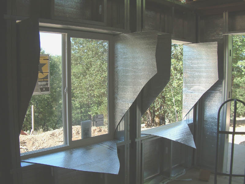
Windows and doors are the next step. When I framed the exterior walls, I played the window rough openings a bit undersize, thinking that the steel studs held straighter lines than 2x lumber, and I was careful with the long carpenter's level. With the insulating wrap cut and folded into the window openings, no shims were required for any of the sixteen windows. Each window required a firm push to slide tightly home to its flanges, and I was struck with organic thoughts of early sex combined with the satisfaction of mature sensuality. A la recherche du temps perdus. |
 |
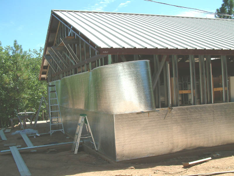
The same low-e insulating wrap is used to isolate the exterior wall steel (studs and red iron) from the siding. In order to install the wrap single-handedly, I put together a device which hangs from the eave struts and allows the wrap to unspool at approximately the correct height to lap the prior layer below. The wrap provides about a R-9 insulating value and is highly reflecting on both sides. 17 July 2004. |
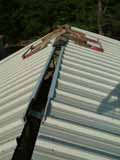 |
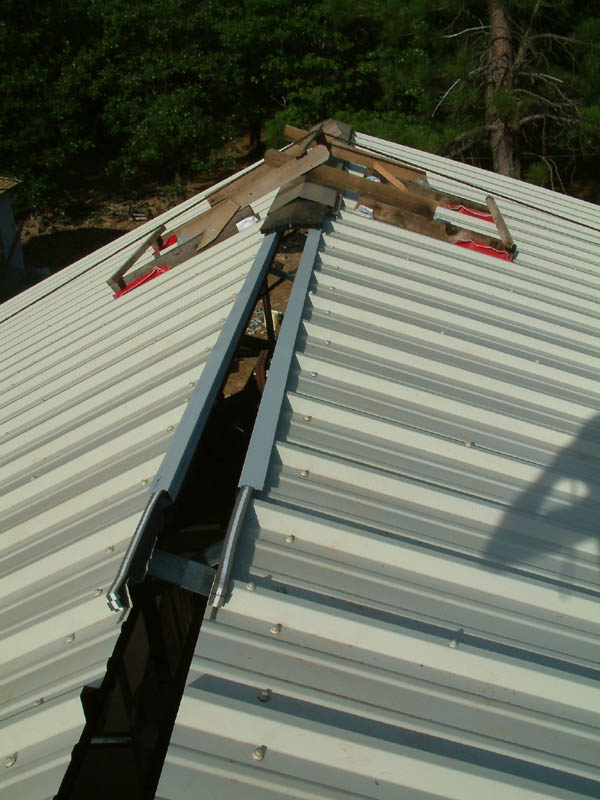
Looking at the ridge line from west to east. I have started to install the ridge cap, seen at the east end under the "ridge bridge" scaffold. Under the ridge cap are sections of black plastic Ridgemaster venting. Below the venting along the two top edges of the panels is a line of foam closure strips, compressed by steel U-trim pieces 10 feet long, gray in color. Compressing the foam closure and simultaneously installing the U-trim is difficult. The U-trim pieces are attached using pop rivets installed from under the panels using scaffolding on the ceiling joists inside.
Moving about and working on the ridge is very strenuous. I constructed the ridge bridge to allow me to drill and drive the ridge cap fasteners (more lap-tek self drillers) with both hands free. |
 |
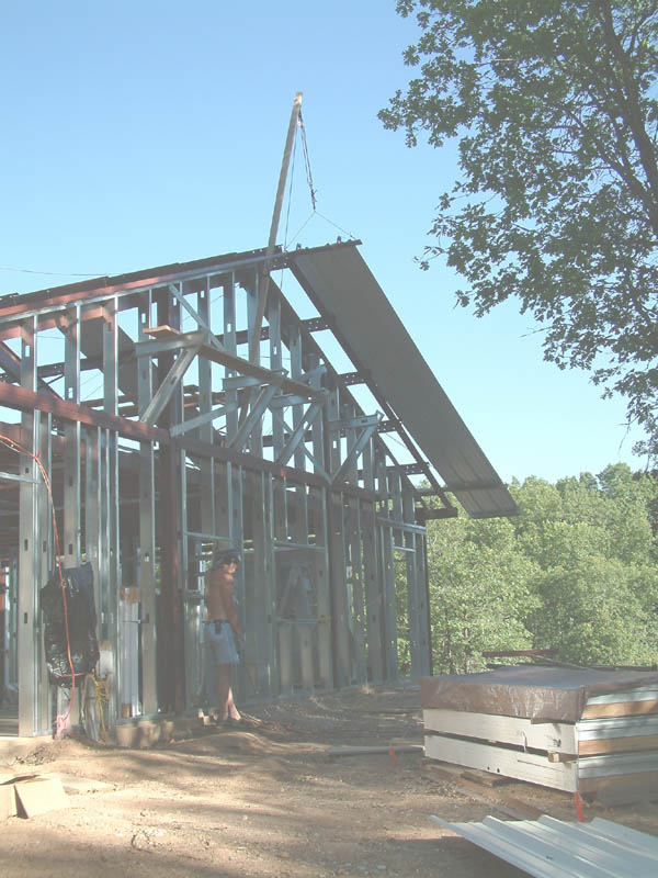
Here the same panel is raised above the slope of the roof. The outrigger 2x4 is visible below the panel near the south end, and the lower derrick has been rotated inboard down into the plane of the roof. I will now climb to the south purlins and pull the lower end of the panel inboard where its lower end will become captive onto a block clamped to the south eave strut. Then I will climb the scaffolding at the center derrick below the ridge and pull/push the upper end of the panel inboard onto the purlins. Once inboard and on the purlins, I will undo the clamps holding the wood 1x4 used to attach the upper block and tackle. Following this the panel is slid to the east by me at the ridge and a helper on a step ladder by means of more blocks secured along the eave strut at the south edge of the roof. |
 |
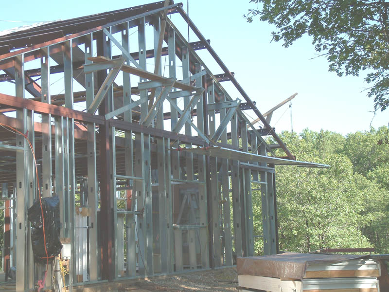
I had to find a way to raise the panels onto the south slope of the roof. My solution was to construct two derricks, one at the center peak and one at a lower purlin, along the west end of the roof. A 2x4 acts as an outrigger in line with a purlin at the lower end. At Jim Wilhelm's suggestion, I made the outrigger retractable toward the east so that the lower end of the panel can be raised using the south derrick above the plane of the roof slope before extending the outrigger. The lower derrick is hinged at the bottom and swings to the east to lie in the plane of the purlins. This allows the panel to be slid to the east onto the slope after it is resting on the outrigger and fully raised by the center high derrick. A safety rope is also clamped to the south end of the panel during raising to prevent a down-slope runaway.
In this image, a panel is raised half way horizontally just below the line of the outrigger. |
 |
A self-timer picture of me ascending the extension ladder leading to the roof "ladder". I am carrying a AC-powered high speed drill and in my belt is the high-torque Milwaukee driller-driver which my brother Andy sent me. I am also carrying oil and the self-drilling lap-tek screws for fastening the panels to the purlins, and a cell phone in case of an emergency. It turns out that each panel uses 34 screws. Because I am Arnold-challenged, to be politically correct about it, I drill a 1/8" pilot hole for each lap-tek screw, using oil to preserve the titanium drills. So the 32 roof panels took over 1000 drilled holes and driven screws.
Arnold (and maybe both Georges) might smile at all that screwing around. |
 |
My neighbor Jim Wilhelm is posing for this picture. Jim gave invaluable assistance and advice during the 5 weeks it took to complete the roof. While I did all work above the bottom of the roof, Jim helped at step ladder height, especially in adjusting the final gutter line (I made blocks to assist in this), and in installing the low-e foil insulation which is installed over the purlins prior to attaching the roof panels. Practically all jobs besides the fastening require two persons, and Jime was my primary associate.
Long 2x4s with attached cleats straddle the ridge and comprise a "roof ladder.
The roofing panels are over 23 ft in length and present a serious challenge to the owner-builder. The roof is the most difficult part of the project so far. |
 |
The bedrooms and bathrooms are located at the east and west ends of the house. I made a major alteration in the design in April, long after the slab was literally "set in concrete". This was the change (originally suggested by Micki Haley) from swinging doors to pocket doors throughout the interior, except for one utility room. This change, which should make the interior even more open, required considerable thought in laying out the tracks and studs to accommodate the pockets because the wall locations and drain pipes had already been literally "cast in concrete".
Here is a view of the internal framing at the west end of the house. The sliding glass doors are stacked at the background. The tracks were attached to the concrete slab using both conventional wedge anchors and powder-assisted nails. My brother, Andy Knapp, introduced me to the 22cal. powder-assisted fastening system for "shooting" nails. Note that I had to be very careful to avoid perforating the slab at the locations of hydronic tubing, which had been arranged to run below internal walls only where doors are located. |
 |
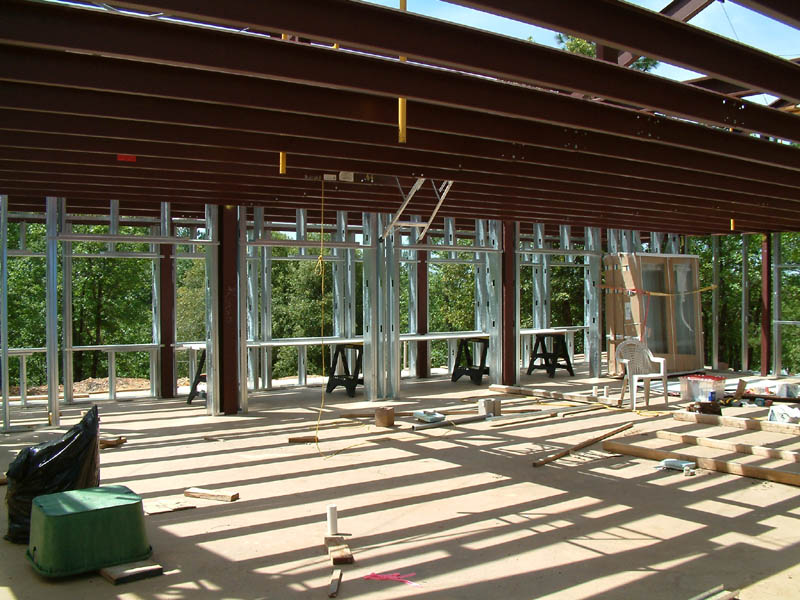
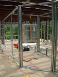
Shown here is the internal south wall, which separates the main living areas from the sunspace. The four large openings are for the sliding glass "patio" doors. The clear span house design is apparent. |
 |
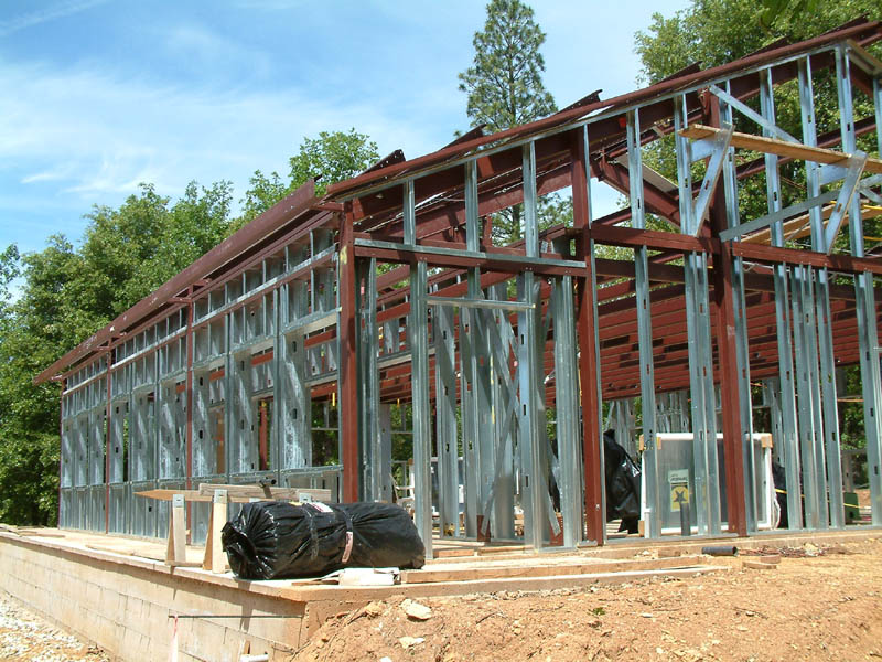
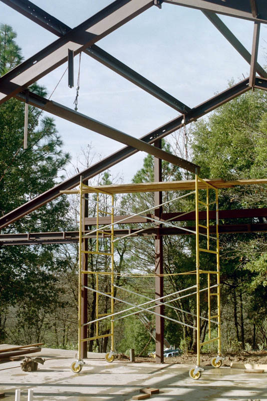
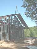
By 14 May I had finished the external framing. This westerly view shows the south facing wall of the sunspace, which has nine 4x4 ft windows. In order to reach under the east and west eaves, where soffits and trim are installed, I had to build the cantilevered scaffolding visible on each end wall under the gable.
Recall that the house design from the steel manufacturer is for a porch on the south. I have chosen to wall in the porch as a sunspace.
Although total rainfall during the rainy season left California still in drought conditions, the rain did slow the progress of the framing. |
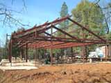 |
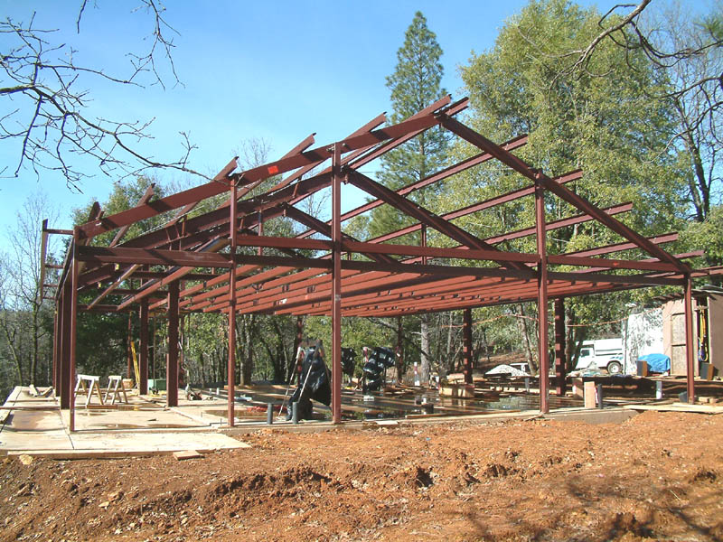
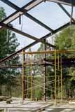
Image taken on 25 January with red iron complete, including ceiling joists. A sense of the internal clear span may be gotten from this floor level view. The next major tasks are to install the external walls, with steel framing for doors and windows, and to attach the steel roof with insulation. |
 |
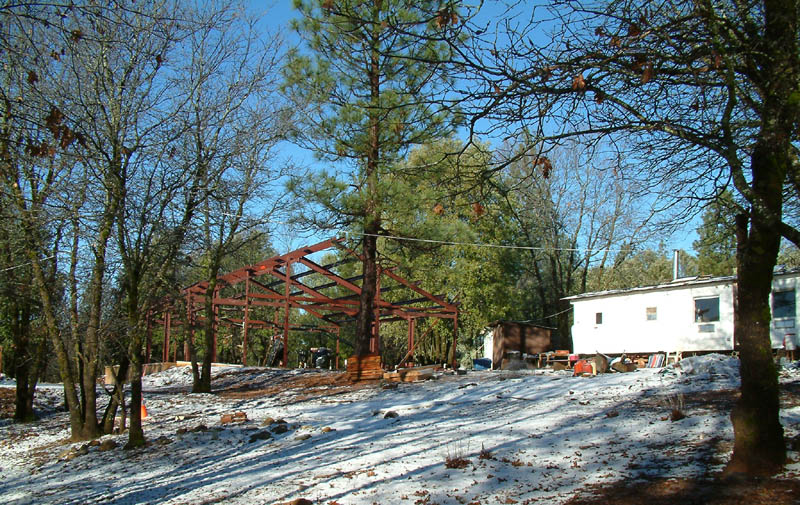
Snow is normally light at the 2500 foot altitude. This postcard image was taken on 03 january 2004. This image was recorded on my new digital camera, a Fujifilm S602 Zoom. |
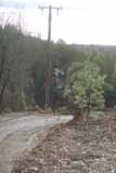 |
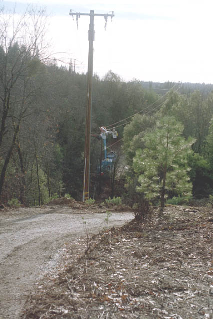
In the distance the PG&E crew are tying into the existing high voltage line at a distribution pole located at the southwest corner of my property. Note the transformer on the new pole. Electric utility power was a terrific Winter Solstice present. Until now I had been using three small lamps of my own construction each consisting of 9 white LED lamps, all powered by my 12v solar pv system. No longer did I have to recharge computer, cell phone, and my electric razor at my neighbor's barn. And I could use my other electronics. I brought 15 amp service to the house trailer. I also "decommissioned my generator" and connected the well pump to the 240 volt service. Because of poor service from SBC I did not receive an installed telephone line until 15 January.
It took many days intermittent work for me to clear the 30 ft wide swath for the 200 foot aerial run to the new pole. I used my 14 inch chain saw, about all that I thought I could handle. There is quite a bit of future oak firewood along the swath. |
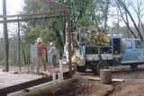 |
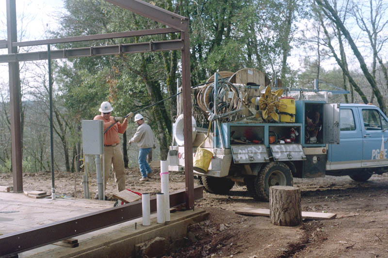
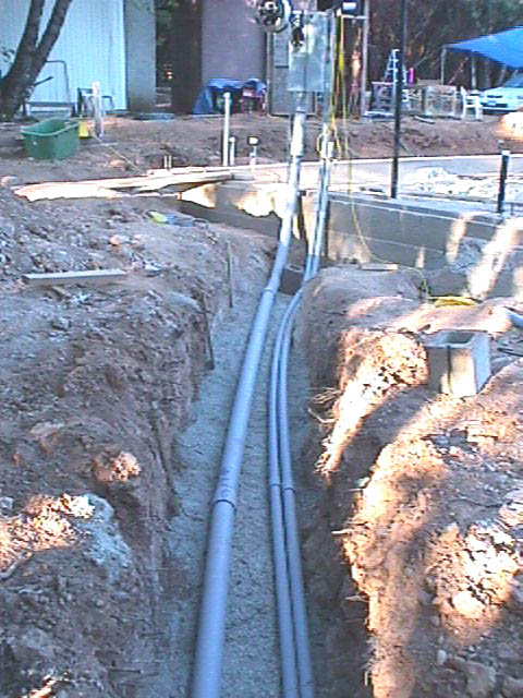
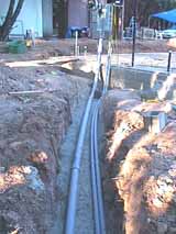
PG&E, the energy utility, arrived on 20 December to bring electric power from the corner of the property to the house site. The run consists of a 200 ft aerial run, an intermediate pole, and a 200 foot trench run from pole to house. Fortunate for me, an existing high voltage distribution line runs along two sides of the property.
The power cable is being fed into the top of the trench conduit by the man in orange. The cable is being drawn by one man at the new pole pulling a nylon lead line which I had left in the conduit per specifications. The pull went without a hitch. |
 |
This photograph, taken on 20 December, shows how it is possible for one determined person, using block and tackle, to raise and install purlins onto the rafters. |
 |
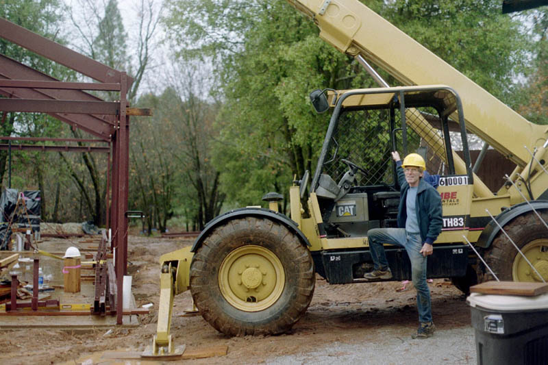
Well, this is learning the telescoping forklift on the job. Note that the tires are filled with water. I was warned not to have a puncture, as the repair (at my cost) would be expensive. Saturday, 6 December.
Everyone got wet in the rain. I have lost at least 5 pounds on this project, I suppose because i don't eat enough calories. I am trying to adjust my diet. |
 |
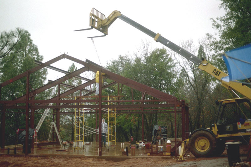
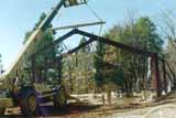
Here is the structure on the morning of Saturday, 6 December. Joe is working hard to install more purlins before leaving. Joe's wife, Vicki, and their two daughters arrived at midday for the return to Southern California. Currently, I am finishing the remaining secondary steel elements with the assistance of Craig. Joe Gamm made this possible. Rain has continued in the following week, and this has made progress on the secondary elements very slow for me (with Craig's help). Four secondary steel elements were fabricated in error and there are two cases of minor interferences between elements. These will require my performing field modifications with compensation from the manufacturer. |
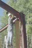 |
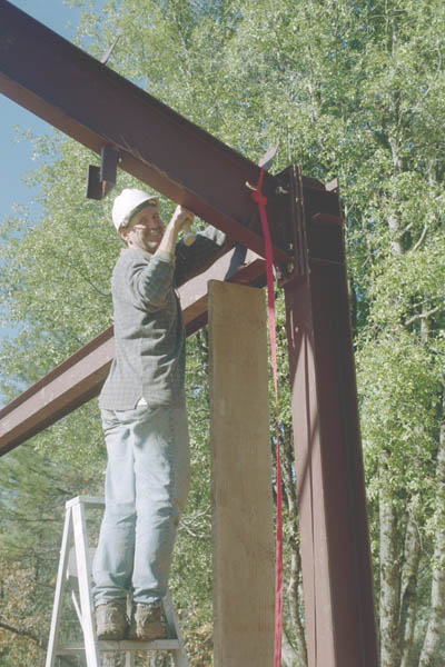
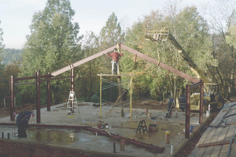
Joe is attaching the rafter to its north column using 7/8" A325 high tension bolts at late afternoon on Thursday, 4 December. There are no surviving images from Friday the 5th, which was rainy all day. Joe worked under difficult conditions atop the scaffolding in the rain. This work went deep into evening twilight. My Sony digital camera appears to have finally died, and the images here starting with the concrete finishing of the slab are from digitally processed 35 mm Kodachrome using my aged Pentax. |
 |
Joe and I decided to use the alternative method for the second primary rafter. We joined it while lying on the slab, and then fashioned a 16 ft "spreader bar" from a 6x6 borrowed from one of my next door neighbors. |
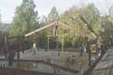 |
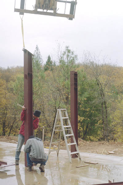
The morning of Wednesday, 3 December 2003. That is Joe atop the scaffolding. The Pettibone is at distant right, holding the half rafter for joining to its partner. |
 |
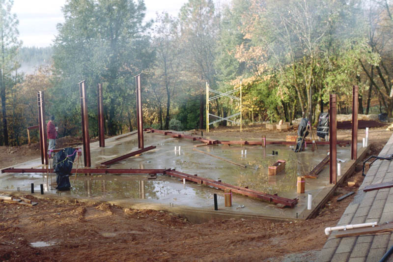
The morning of Tuesday, Dec 2. We had no problems with the concrete anchor bolts. I am most pleased and proud that they were located correctly. The columns of the primary, structural, central bay are in place. South is to the left. The three bays run E-W. The four halves of the two main rafters are ready on the slab for erection. Recall that this view is from the roof of the trailer in which I live. The smoke is from the wood stove. |
 |
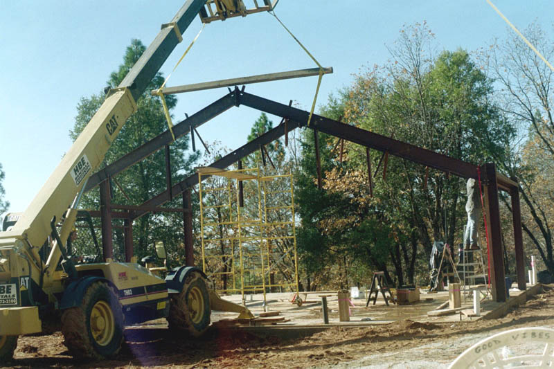
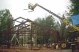
The main steel structural elements were erected during the week of Monday, December 1. My friend Joe Gamm (red jacket) came up from Ventura county and stayed until Saturday the 6th. Without Joe's presence, common sense, and unmeasurable hard work in very tricky circumstances, the job would have taken much more time and resources. We were assisted by Craig, a local handiman. Most of the time I was operating a very large rented telescoping forklift (called a "Pettibone"). Here Joe and Craig are bolting one of the primary columns to support one of two large rafters for the central and primary bay. That is the end of the Pettibone arm and fork lowering the column. More than half the week we worked in rain. |
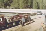 |
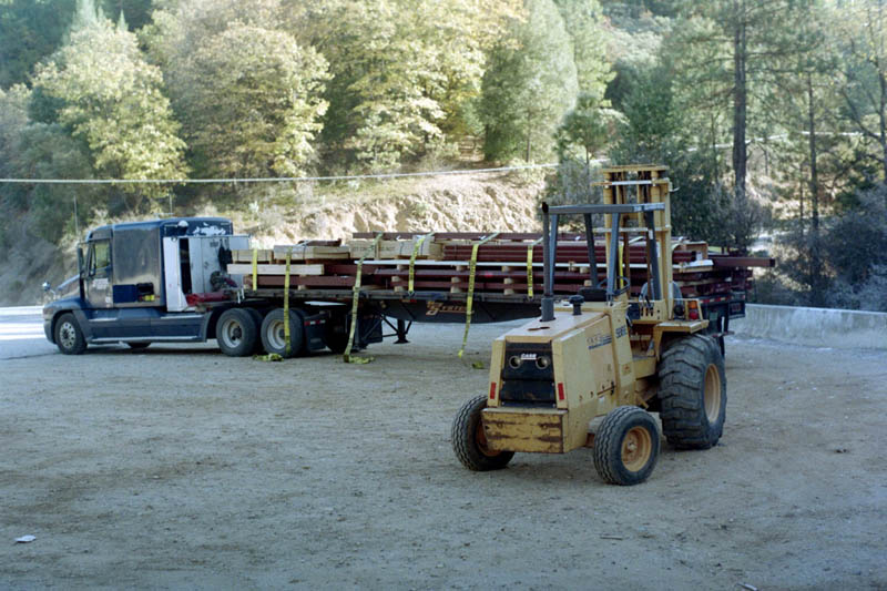
Time was critical, and the flat bed truck was the tippable kind, used mainly to carry vehicles. It took three loads to move the more than 16,000 lbs of steel to the house site. The steel suffered a few dings when the flat bed was tipped to slide the loads off. The worst seems to have been some twisting of the purlin steel "Zs", which twisting makes the bolting of the purlins atop the rafters a bit more tricky. |
 |
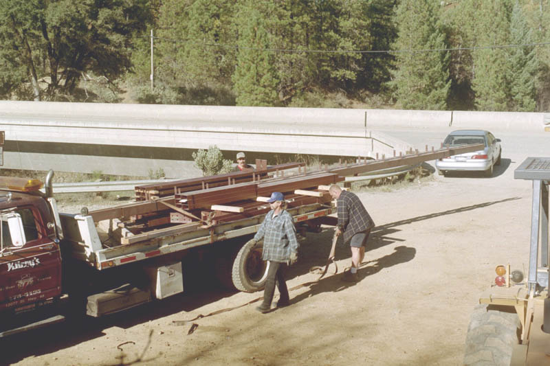
Finally, after several delays, the house steel arrived on Monday, 26 November. By prior arrangement, I met the load in this parking area, about a mile from my property. The driver refused to bring his rig off the paved road when I drove him to inspect the access road and driveway, even though slightly smaller tractor-trailers had made it, including the one which delivered the rented forklift. So I drove the forklift down to the truck, and called for a flat bed truck for transshipment. |
 |
Here is the finished foundation on 21 October 2003. A total of 69 cubic yards was used in both pours. It turned out to be a day of record-setting high temperature (21 October). The team, on knee boards, had to work very fast and strenuously to finish the slab surface before the concrete set hard. The concrete was unworkable by 2PM, when the crew stopped. The slab is colored to match the color used in the earlier foundation pour.
The next events are the delivery of the steel, and the installation of electric service, both expected near the week of 17 November. |
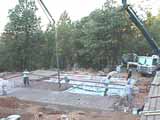 |
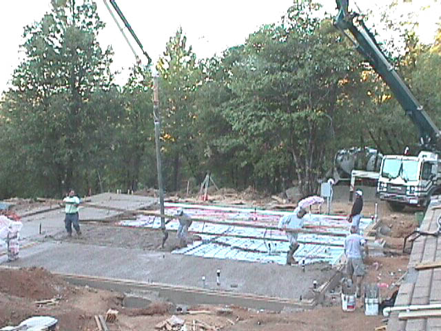
The pumper and boom can be seen. Two men are removing one of the long boards used to set the slab height while the concrete is being poured in the middle swath. The sunlight is overexposed in the far background. |
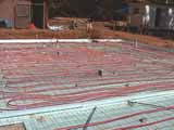 |
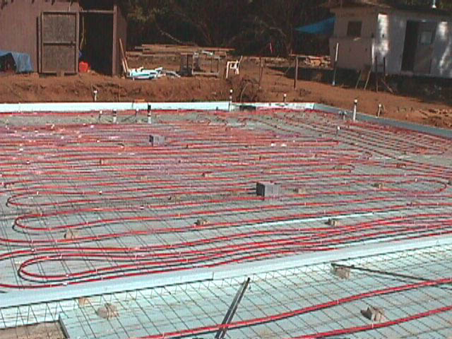
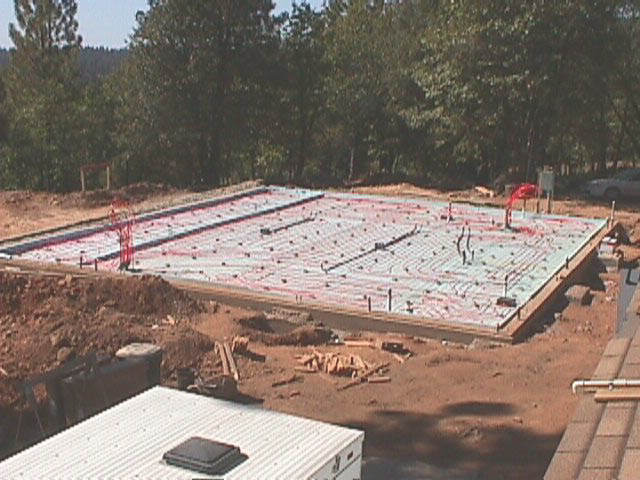
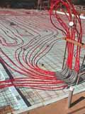
View from the southwest of the sunroom looking toward the northeast. Note the rebar at image bottom which connects the mesh to the large concrete piers in the first pour. Just under 2000 feet of 1/2 inch PEX tubing was installed for the hydronic system.
Not shown in these photographs are ten buried temperature sensors (current proportional to degrees K) and cables terminating at the northwest corner. The sensors, produced by my colleague Douglas Niessen, are tied to the mesh adjacent to the tubing. The sensors will report the temperatures at the tubing within the concrete, at strategically chosen locations throughout the slab. |
 |
The hydronic tubing loops terminate at two future manifolds, at the nW and SE corners of the slab. This is the hydronic tubing at the southest corner. Note the styrofoam "wall" at lower left, made from two layers of foam sandwiching the welded wire mesh. This wall is intended to be a thermal break in the slab for isolating the sunroom along the south face of the house from the living room and master bedroom. At this time the sunroom is not heated, although I have laid tubing in two loops, seen crossing the wall, in it for possible future use (which might possible include passive solar heat). Note the pressure guage. The hydronic tubing is connected in series and pressurized to about 80 lbs/ sq.in. for the county building inspection and for the concrete pour and cure. |
 |
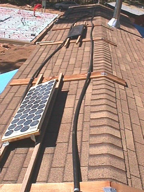
Life will be a bit austere until next spring or so. This is the roof of the old trailer where I live. I have two solar pv panels, amounting to around 80 watts, feeding two deep cycle marine batteries. I normally use white LEDS for light at night. Also visible is some of the 100 feet of 1" black poly pipe which supplies about 4 gallons of warm to hot water when it is not cloudy. One of my neighbors has lent me a wood stove and one of the pv panels. The house slab is visible at upper left.
[Pg&E power was brought in, with a new power pole at the end of the trench, just before Christmas, 2003.] |
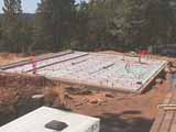 |
It took nearly three days for me to place the hydronic tubing. I had previously layed out the design of 15 separate hydronic loops and calculated their thermal and hydraulic properties. There are a number of design conditions which the loops and the entire system must satisfy, and the system should also accommodate specific requirements associated with the architecture. Examples of the latter are higher floor temperatures for the bathrooms and increased surface density of tubing near windows and the sliding glass doors. |
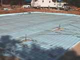 |
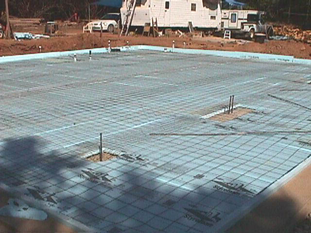
Over the insulation goes a layer of #10x6"x6" welded wire mesh, which is steel reinforcement for the slab. The hydronic tubing will be secured to the mesh with cable ties and the mesh will be supported 2" above the insulation on several hundred "dobies". The dobies put the mesh and the hydronic tubing near the center of the slab. |
 |
The slab grade has been finished with subslab rock followed by a shallow covering of washed sand. I have covered the sand with a 6-mil poly vinyl vapor barrier sheet. In this image I am half way through adding a layer of 2" polystyrene insulation over the vinyl and also around the perimeter. This is to thermally isolate the floating concrete slab with embedded hydronic radiant heating tubing, to be added shortly. |
 |
A view of the power trench with 3" conduit for the PG&E cable and two 1.5" conduits for telephone and a spare. The meter and main switch box is installed on temporary struts until the wall is erected. The spool for the large tape for pulling the power cable is visible. This section of the trench is about to be covered to make a bridge for the Kuboda backhoe used to prepare the slab.
[The trench was completed after the final slab pour, at the end of October. The trench was inspected and approved by PG&E, and a neighbor did the back filling of the trench with his backhoe.A layer of sand will be added above the conduits before the back filling. PG&E will finish the interface between the conduit and the pole and the far end of the trench,which is about 175 feet long.] |
 |
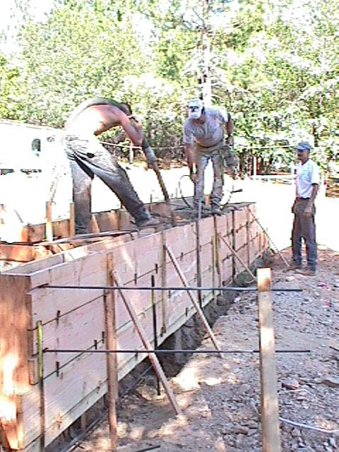
Deep exposure in tree shadow of the pouring of the concrete into the retaining wall. Nearest is the operator of the concrete pump, holding the heavy hose from which the mix is shooting. Contractor Mike Verbeke is plunging the concrete vibrator to remove entrapped air and settle the aggregates. Do not confuse this vibrator with the vibrators of the Burning Man theme camp; concrete vibrators are NOT for personal use.
The rebar and a conduit (not visible) are for the future patio, if it happens. The last two deliveries (of four) were colored. This color is "sandstone", and it is what the house slab floor will match. I intended to have a redder color, more like the soil, but in the end I went more conservatively. At least it is not gray (the buried concrete is not colored). |
 |
The morning of the inspections of the foundation and rough plumbing (drain, waste, vents). The inspector arrived late, at 2PM. Everything passed, and Mike Verbeke, the concrete contractor, immediately called for the concrete ready mix deliveries. I did all the plumbing. |
|
Final forming of the retaining wall. Note engineering including rebar tying the retaining wall to the large piers. Drain rock will go in the cavity to the right of the retaining wall. I am standing at the slab level. Below the retaining wall will go a patio planned to be about 57 feet long by 16 feet wide. |
|
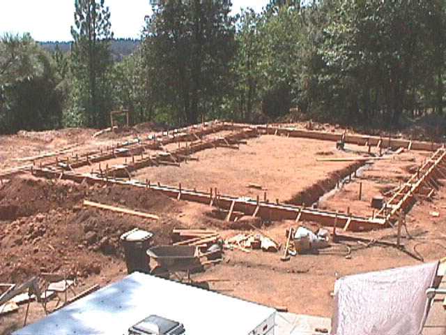
Trenching in progress, 15 May 2003. The steel construction requires 20 concrete foundation piers for the steel structure, the central six of which are very massive. In addition are the plumbing drain trenches, a trench connecting the house main sewer pipe to the septic system 75 feet away, and a 185-foot long trench which will carry the electric power and telephone to the house. Other trenches will bring in water from the well system and propane from a tank. Just visible are some of my survey flags and paint lines. |
|
|